Working Principle of Surface Stabilized Orthogonal Anti-Ferroelectric liquid crystal display
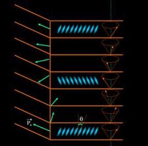
Fig. 1 Ferroelectric liquid crystal
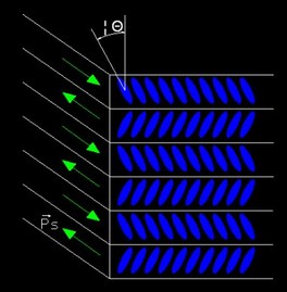
Fig. 2 Unwounded antiferroelectric liquid crystal
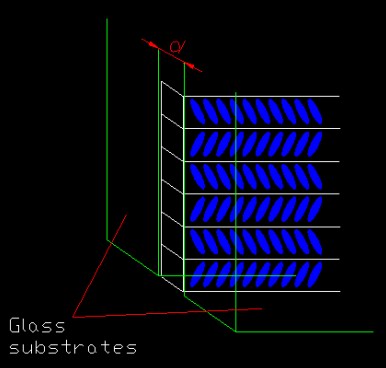
Fig. 3 Surface stablized antiferroelectric liquid crystal.
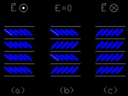
Fig. 4. Molecule director of SSOAF LC affected by different electric field.
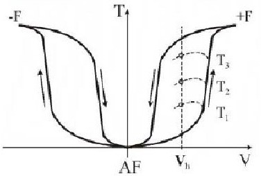
Fig. 5. Curve of transmittance versus voltage applied on SSOAF LC panel.
|
1. Ferroelectric liquid crystal
Ferroelectric liquid crystal refer to the liquid crystal possesses macroscopic electric polarization. This kind of polarization is intrinsic to the material itself, which is also called sponteneous polarization, symbolized as Ps. There is no Ps at any direction if the molecule and structure of the material are totally symmetrical at any direction. The rod-shaped molecule of the ferroelectric LC is not symmetrical and possess polarization along a certain direction perpendicular to its axes. If there is no external force, the molecules have a layered helical structure as shown in Fig. 1. The helical structure is the lowerest energy state for the asymmetrical molecules. Although there is polarization for each individual molecule, they are cancelled each other due to the helical structure. Hence there is no macroscopic plarization for the material. Nevertheless, if the helical structure is unwounded by external force, the material will possess macroscopic polarization, and has ferroelectric property. 2. Surface Stabilized Orthogonal Antiferroelectric liquid crystal With helical structure unwounded, some liquid crystal materials render a kind of structure shown in Fig. 2. The direction of Ps in each neighbouring layer are opposite each other. This kind of material is called antiferroelectric liquid crystal. For the antiferroelectric liquid crystals whose Θ is 45°, i.e., the angle formed by the molecules in the neighbouring layer is 90°, they are called orthogonal antiferroelectric liquid crystal. Normally, for the display application, the external force used for unwounding the helical structure of liquid crystal is provided by the interaction between the liquid crystal molecules and the specially treated surface of glass substrates. The two glass substrates and the liquid crytal form a sandwich structure as shown in Fig. 3. For unwounding, the thickness of the liquid crystal has to be smaller than the pitch of the helical structure on its natural condition . We call the orthogonal antiferroelectric liquid crystal unwounded in this way as Surface Stabilized Orthogonal Anti-Ferroelectric liquid crystal (SSOAF LC). 3. Working principle of SSOAF liquid crystal display When the electric field applied to the SSOAF liquid crystal cell equal to zero, the molecular structure is shown in Fig. 4 (b). As there is no mecroscopic birefringence for the structure, there is no light transmittance through the cell in between two orthogonal polarizers. This is the dark state. When there is electric field high enough (normally tens of volt) applied to the cell, the SSOAF liquid crystal molecule directors will render either Fig. 4 (a) or (c) depending on the direction of the electric field due to the interaction with the spontaneous polarizer Ps. In this case, the liquid crystal layer can serve as a half-wave plate, and the polarization of the incident light beam will be turned 90° and pass through the opposite polarizer. This is the bright state. Fig. 5 shows the transmittance versus voltage applied on SSOAF LC panel. |
Measurement of the response time of SSOAF liquid crystal cell
Driving signal
As the driving voltage for SSOAF LC need tens of volt, so higher driving voltage signal has to be used. A two- chennel arbitrary waveform generator with P-P value 10v is used together with an amplify can output waveform to maximum P-P of 200 volt.
Another Multiway driving signal generator can be used to generate multiway driving signal up to 36 volt, which can be used for the driving of multi-pixel SSOAF LC display panel.
Signal connection
An ultrasonic soldering system, which can solder on glass substrate, was used to solder the wire to the ITO panel when applying driving voltage to the SSOAF LC panel.
|
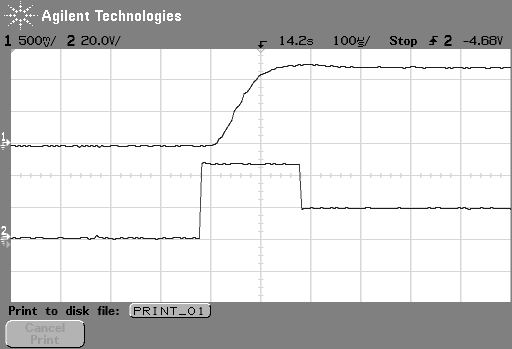
Response time measured for SSOAF LC cell
As shown this figure, bottom part is the driving voltage, upper part is the transmittance measured. It can be seen that the response time measured for the SSOAF LC cell is about 100us, which is much shorter than the ms for normal LCD cell. |
